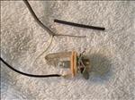
The input jack with part of a test wire I soldered.
100-Install-Input-Jack.JPG |
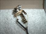
The shielded wire solderd to the input jack.
101-Install-Input-Jack.JPG |
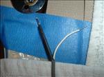
The wire tips tinned.
102-Install-Input-Jack.JPG |
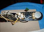
The switch assembly wired.
103-Install-Input-Jack.JPG |
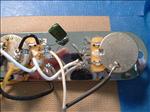
Negative (black) connection to the bottom of the tone pot and the hot (white) connection to the center connection on the volume pot.
104-Install-Input-Jack.JPG |
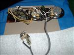
The input jack connections complete
105-Install-Input-Jack.JPG |
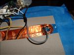
Inserting the input jack into the body.
106-Install-Input-Jack.JPG |
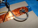
Inserting the input jack into the body - part 2.
107-Install-Input-Jack.JPG |
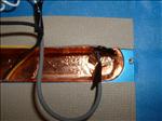
Some patience and a small pair of needle nose pliers came in handy.
108-Install-Input-Jack.JPG |
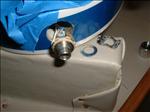
The input jack outside of the body.
109-Install-Input-Jack.JPG |
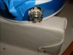
Notice the flange with the "bent" sides.
110-Install-Input-Jack.JPG |
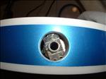
Setting the input jack in the body cavity
111-Install-Input-Jack.JPG |
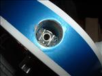
The input jack in the input jack recess in the body
112-Install-Input-Jack.JPG |
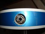
A close-up of the damaged edges around the input jack opening on the body.
113-Install-Input-Jack.JPG |
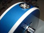
The cover and cover nut on the input jack.
114-Install-Input-Jack.JPG |
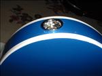
The cover and cover nut on the input jack - side view.
115-Install-Input-Jack.JPG |
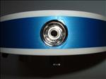
Another view of the input jack cover.
116-Install-Input-Jack.JPG |
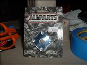
The new input jack cover plate - similar to the Les Paul square cover plate. [Added 10/24/06]
117-Install-Input-Jack.JPG |
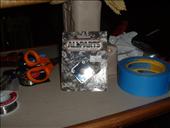
The new input jack cover plate - package view. [Added 10/24/06]
118-Install-Input-Jack.JPG |
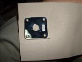
The underside of the jack placed on rubber matting. [Added 10/24/06]
119-Install-Input-Jack.JPG |
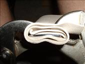
Bending the cover plate jack. [Added 10/24/06]
120-Install-Input-Jack.JPG |
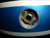
The old ugly chipped input jack hole. [Added 10/24/06]
121-Install-Input-Jack.JPG |
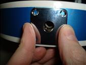
Test fitting the cover plate after some gentle bends. [Added 10/24/06]
122-Install-Input-Jack.JPG |
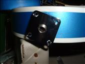
Placing the cover plate over the threaded part of the input jack. [Added 10/24/06]
123-Install-Input-Jack.JPG |
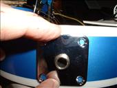
Checking the fit over the input jack and against the guitar body. [Added 10/24/06]
124-Install-Input-Jack.JPG |
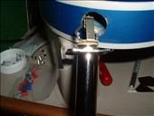
Attaching the input jack to the cover plate. [Added 10/24/06]
125-Install-Input-Jack.JPG |
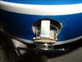
The cover plate attached to the input jack. [Added 10/24/06]
126-Install-Input-Jack.JPG |
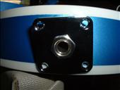
Test fit against the body - it covers all of the chips. [Added 10/24/06]
127-Install-Input-Jack.JPG |
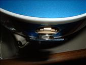
Top view of the plate attached to the input jack. [Added 10/24/06]
128-Install-Input-Jack.JPG |
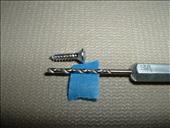
Setting the depth of the drill bit against the mounting screw. [Added 10/24/06]
129-Install-Input-Jack.JPG |
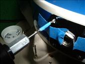
Drilling the first mounting screw hole. Notice the tape... [Added 10/24/06]
130-Install-Input-Jack.JPG |
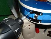
Another view of drilling the screw hole. [Added 10/24/06]
131-Install-Input-Jack.JPG |
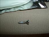
Coating the screw with soap - it makes it much easier to install. [Added 10/24/06]
132-Install-Input-Jack.JPG |
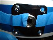
The first screw set and the second screw hole drilled. [Added 10/24/06]
133-Install-Input-Jack.JPG |
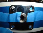
Another view… [Added 10/24/06]
134-Install-Input-Jack.JPG |
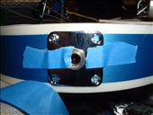
Another view… [Added 10/24/06]
135-Install-Input-Jack.JPG |
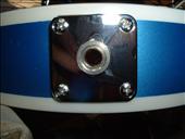
All four screws installed. [Added 10/24/06]
136-Install-Input-Jack.JPG |
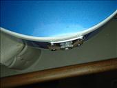
Top view of the mounted cover plate. No gaps between it and the body… [Added 10/24/06]
137-Install-Input-Jack.JPG |
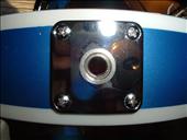
Another front view of the mounted cover plate. [Added 10/24/06]
138-Install-Input-Jack.JPG |
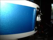
Left side view of the mounted cover plate. Looks good... [Added 10/24/06]
139-Install-Input-Jack.JPG |
The other side view of the mounted cover plate - no gaps. [Added 10/24/06]
140-Install-Input-Jack.JPG |
