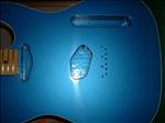
The empty pickup and switch cavities.
100-Pickup-Cavities.JPG |
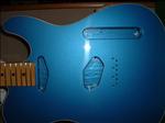
Another shot of the unshielded pickup and switch cavities.
101-Pickup-Cavities.JPG |
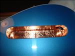
The switch cavity with copper shielding.
102-Pickup-Cavities.JPG |
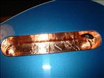
Step-2 in applying the copper foil.
103-Pickup-Cavities.JPG |
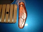
The rhythm pickup cavity.
104-Pickup-Cavities.JPG |
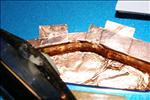
Extended the foil on the rhythm cavity.
105-Pickup-Cavities.JPG |
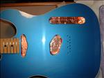
All cavities with foil shielding.
106-Pickup-Cavities.JPG |
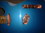
Another view of the shielded cavities.
107-Pickup-Cavities.JPG |
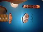
Another view of the shielded cavities.
108-Pickup-Cavities.JPG |
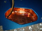
Testing the fit of an eyelet for ground wire in the neck pickup cavity. [Added 10/24/06]
109-Pickup-Cavities.JPG |
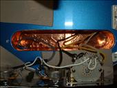
The control cavity before extending the shielding. [Added 10/24/06]
110-Pickup-Cavities.JPG |
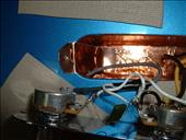
Fitting a piece of copper foil tape to one end of the control cavity. [Added 10/24/06]
111-Pickup-Cavities.JPG |
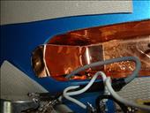
A close-up view of the end piece of foil tape. [Added 10/24/06]
112-Pickup-Cavities.JPG |
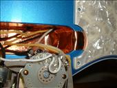
I repeated the process for the right side of the control cavity. [Added 10/24/06]
113-Pickup-Cavities.JPG |
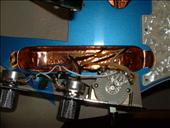
A view of both ends of the control cavity with the extended copper foil tape. [Added 10/24/06]
114-Pickup-Cavities.JPG |
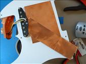
Measuring and test fitting the copper foil extension to run form the neck pickup cavity to the edge of the control plate. [Added 10/24/06]
115-Pickup-Cavities.JPG |
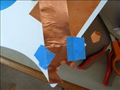
Trimming the foil to match the pickguard contour. [Added 10/24/06]
116-Pickup-Cavities.JPG |
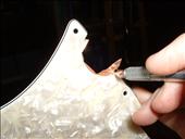
Trimming the copper foil tape. [Added 10/24/06]
117-Pickup-Cavities.JPG |
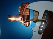
Fitting the foil tape extension in the neck pickup cavity. [Added 10/24/06]
118-Pickup-Cavities.JPG |
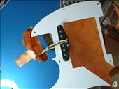
The copper foil tape attached to the pickup cavity and the pickguard. [Added 10/24/06]
119-Pickup-Cavities.JPG |
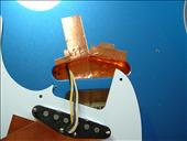
Another view of the neck pickup cavity and pickguard with copper foil tape. [Added 10/24/06]
120-Pickup-Cavities.JPG |
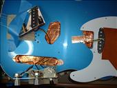
All of the cavities and pickguard with the additional copper foil tape in place. [Added 10/24/06]
121-Pickup-Cavities.JPG |
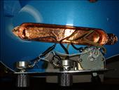
The finished pieces of foil tape for the control cavity. [Added 10/24/06]
122-Pickup-Cavities.JPG |
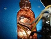
Soldering the connection point for the copper foil on the left side in the control plate cavity. [Added 10/24/06]
123-Pickup-Cavities.JPG |
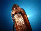
A close-up view of the first solder connection. [Added 10/24/06]
124-Pickup-Cavities.JPG |
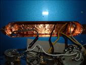
The finished control cavity. I soldered two connections - one at each end. [Added 10/24/06]
125-Pickup-Cavities.JPG |
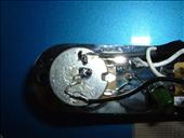
Attaching the extra ground wire to the bottom of the Tone pot. [Added 10/24/06]
126-Pickup-Cavities.JPG |
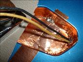
Soldering the connection point for the copper foil pieces in the neck pickup cavity. [Added 10/24/06]
127-Pickup-Cavities.JPG |
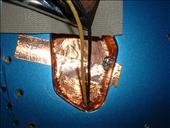
Another view of the solder connection in the neck pickup cavity. [Added 10/24/06]
128-Pickup-Cavities.JPG |
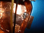
A close-up of the solder connection in the neck pickup cavity. [Added 10/24/06]
129-Pickup-Cavities.JPG |
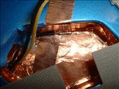
Placing the ground wire, from the Tone pot, in position so that a solder joint will connect the wire to the two pieces of foil tape. [Added 10/24/06]
130-Pickup-Cavities.JPG |
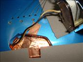
Another view of the ground wire placement in the neck pickup cavity. [Added 10/24/06]
131-Pickup-Cavities.JPG |
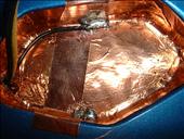
The ground wire soldered in place. [Added 10/24/06]
132-Pickup-Cavities.JPG |
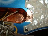
The foil tape on the right side of the control cavity extending under the pickguard. [Added 10/24/06]
133-Pickup-Cavities.JPG |
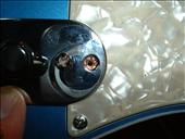
Setting the control plate in place. [Added 10/24/06]
134-Pickup-Cavities.JPG |
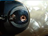
A close-up of the foil tape under the right side of the control plate and pickguard. [Added 10/24/06]
135-Pickup-Cavities.JPG |
A close-up of the foil tape under the left side of the control plate. [Added 10/24/06]
136-Pickup-Cavities.JPG |
