Home
Parts List to Build a Telecaster
Guitar Workstation
Warmoth Telecaster Body
Warmoth Birdseye Maple Telecaster Neck
Gotoh Kluson Tuners
Installing String Ferrules
Installing the Fender Vintage 3-Saddle Bridge
Shielding the Pickup Cavities
Assembling the Switch and Pots to Control Plate
Wiring the Pickups, Input Jack, Switch and Pots
Wiring the Pickups
Installing Input Jack
Installing Pickguard
Dressing the Frets
Installing the Strap Pegs
Guitar Set-Up
Finished Guitar Pics
Overview of Complete Building Process
Resources and Links
Guitar Parts  Calculator
Website Details
Building a 1963 Vintage Lake Placid Blue Telecaster - Bridge Assembly
Click on each image below for a larger view.
This part of the project can be like dealing with voodoo - sometimes it works and sometimes it doesn't. I thought about presenting pictures after each wire was connected but I realized that would be a) a whole lot of pictures; and b) I am by no means an electronics wizard. Instead I thought an overview of what the switch and pots look like when wired along with some tips on wiring the input jack would suffice for this section.

I thought using a 4-way switch would offer much more tonal capabilities so I readily embraced this task. What I found was a plethora of wiring diagrams for the Tele-4-way-switch - each claiming to be the "correct" way to wire the set-up. I settled on the wiring diagram that came with the Fender pickups - and that appeared to be a wise choice.


Building a 1963 Lake Placid Telecaster - Home
100-Wiring-Pots-Switch.JPG
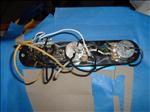
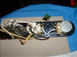
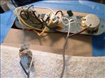
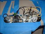
The switch-pot assembly wired.

100-Wiring-Pots-Switch.JPG
101-Wiring-Pots-Switch.JPG
My test wiring.

101-Wiring-Pots-Switch.JPG
102-Wiring-Pots-Switch.JPG
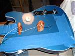
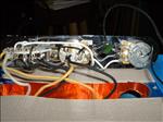
The wiring assembly resting on the guitar body.

102-Wiring-Pots-Switch.JPG
103-Wiring-Pots-Switch.JPG
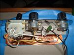
Top view of the switch-pots assembly

103-Wiring-Pots-Switch.JPG
104-Wiring-Pots-Switch.JPG
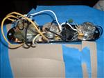
Another view of the wired assembly.

104-Wiring-Pots-Switch.JPG
105-Wiring-Pots-Switch.JPG
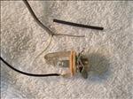
Close up of the wire ends and the input jack.

105-Wiring-Pots-Switch.JPG
106-Wiring-Pots-Switch.JPG
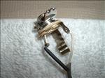
The input jack with the shielded wire attached.

106-Wiring-Pots-Switch.JPG
107-Wiring-Pots-Switch.JPG
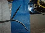
The tinned wire ends of the input jack shielded wire.

107-Wiring-Pots-Switch.JPG
108-Wiring-Pots-Switch.JPG
Switch-pot assembly - partially wired.

108-Wiring-Pots-Switch.JPG
109-Wiring-Pots-Switch.JPG
Switch-pot assembly with the input jack connected.

109-Wiring-Pots-Switch.JPG
110-Wiring-Pots-Switch.JPG
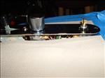
Switch-pot assembly - side view.

110-Wiring-Pots-Switch.JPG
111-Wiring-Pots-Switch.JPG
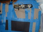
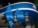
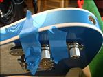
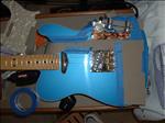
Taping the control plate with switch-pot assembly to the body to test.

111-Wiring-Pots-Switch.JPG
112-Wiring-Pots-Switch.JPG
Using the tape allows quick access to the wiring if you need to resolder or reposition a connection.

112-Wiring-Pots-Switch.JPG
113-Wiring-Pots-Switch.JPG
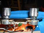
The knobs for the volume and tone pots.

113-Wiring-Pots-Switch.JPG
114-Wiring-Pots-Switch.JPG
The control plate with the volume know attached.

114-Wiring-Pots-Switch.JPG
115-Wiring-Pots-Switch.JPG
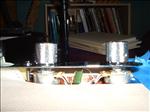
The reset tone and volume knobs - no major gap or visible nut under the knobs.

115-Wiring-Pots-Switch.JPG
116-Wiring-Pots-Switch.JPG
The "two string" test.

116-Wiring-Pots-Switch.JPG
117-Wiring-Pots-Switch.JPG
Another view of the "two string" test.

117-Wiring-Pots-Switch.JPG


All Photos (unless otherwise noted) Copyright © 2006, HiggyDude and Bobby Jean Enterprises
Website - Copyright © 2006, HiggyDude and Bobby Jean Enterprises